
It’s been an eternity since my last posting, but I am going to use this site for sharing pictures of woodworking projects.
At some point I will expand this post possibly to detail the individual projects, but for now i wanted to show these to a few of you. my captions will hopefully give you a rough idea what each picture is depicting.
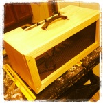
Amplifier Header Cabinet


-

- Finished with rounded edges and corner braces
-

- Finished with rounded edges and corner braces
Picture Frame for a Christmas Gift
-

- A view of the routed profile of the frame

-

- Test miter joints
-
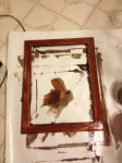
- Staining up the frame
-

- Frame with Stain
-
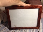
- Completed Frame
-

- Finished Frame with artwork
Wood Burning
-

- Climb High Don’t Die! A birthday gift for my uncle, a mountain climber who scaled all the major mountains listed on this board, and more.
-

- A chicken I made for my grandmother
-

- A flamingo i made for my girlfriend, who is obsessed with flamingos
Router Pantograph and Signs made from it
-

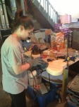
- Setup
-

- Router Setup as seen with tracing screw on the pattern
-

- First letter crved
-
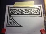
- Close up on the Celtic font pattern
-

- Close up on the celtic letter carving
-

- Sign in its unpainted state
-

- Final painted and stained sign
Crankie Moving Puppet Show
-

- Corner Joint Clamping scheme
-

- Empty frame
-
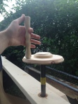
- Completed crank handles
-
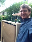
- Completed cranks– with me for scale
-

- Completed with blank screen
Trivets
-

- Painted Tile
-

- Trivet after gluing (pic of finished with tung oil and polycryilic laquer to come soon!)
-

- Cut mitered and rabbeted frame sections of Maple for trivet
-

- Rough assemblage of trivet #1
-

- Clamping up trivet # 1
-

- Twins!
-

- Trivets with tiles for a preview
Majora’s Mask replica
Note: this one is still a work in progress and the pics are only half the story. we are working off this instructable: http://www.instructables.com/id/The-Legend-of-Zelda-Majoras-Mask-Replica/?ALLSTEPS
-

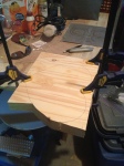
- three 3/4″ boards laminated together
-

- Boards clamping to dry
-
- Partial cutout of initial shape
-

- Cutout of initial basic shape outline
-

- Shaping roughly with a chisel
-

- Shaping with high grit sandpaper and orbital sander
-

- Shaping with high grit sandpaper and orbital sander
-
- Shaping with high grit sandpaper and orbital sander
-

- Shaped and sanded wood blank
-

- Beginning the first primer coats
-

- More painting
-

- Painted with primer
-

- Routing channels for tubing for facial feature relief
-

- Begining to fit the tubing in with epoxy
-

- All tubing in and drying
-

- Result of the tubing
-

- Tubes in with paint
These have been all the wood working projects worth any mention. there’s a few more in the planning stages and I may be gearing up to collaborate on a series of introductory courses.
-M-


